.png)

Key Takeaways
- The majority of frame misalignment is caused by a number of small errors rather than a single large error, over a period of time during the erection process.
- All the columns and rafters that follow are anchored by the accuracy of the anchor bolt and the levels set on the top of the concrete.
- Structural erection drawings in Australia are coordinated, sequencing is clear, and bracing decisions are timely, keeping the frame stable during erection.
- Preventing cladding and services from being out of alignment from occurring is much less expensive than rework after the cladding and services are installed.
Why does steel frame alignment matter during PEB Erection?
Pre-engineered buildings use lightweight pieces that come together with very little room for errors in positioning. When the frame shifts so that it is no longer in the right place, the consequences will typically extend far beyond the frame itself. The cladding panels, girts, roof sheets, and even the doors depend on keeping straight lines and planes. Hence, even a minimal error can create a situation that necessitates costly rework once the envelope installation begins.
Alignment matters for structural performance as well. For example, columns that tilt or lean out of the plumb have eccentric loads, and the elements that have to be forced into position bear stress that the design did not foresee. Therefore, construction teams working on the erection stage consider the alignment not only from the aesthetic angle but also as a structural check. Moreover, the straight frame allows for the faster completion of the following stages, as there is no need to stop every few bays to make adjustments.
How does misalignment show up on site?
Misalignments often become apparent through a couple of common indicators. For instance, the first indicator noticed by the construction team may be the panels failing to fit onto their supports during the sheeting process or the doors that do not close properly.
- Tilt leads to columns leaning out of plumb, which may thus be identified.
- Rafters or the frames are misaligned, producing unwanted slopes and offsets.
- Anchor bolts do not fit the holes in the base plates, thus causing changes that were not planned for originally.
- Purlins and girts do not match the cleats, which causes trouble with the sheeting.
- Door and window openings are not within the necessary tolerances.
Explain the main causes of steel frame alignment problems
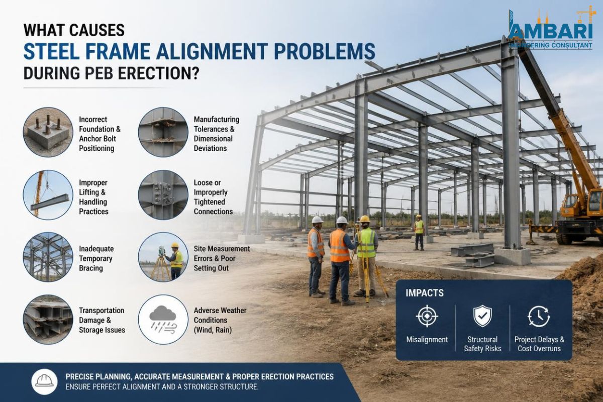
Misalignment hardly ever has just one reason. Most of the time it results from one or more of the following: foundation problems, variations in the manufacturing processes, different types of assembly sequencing, and environmental conditions on site. Knowing the source for each reason allows the team to detect and address the right issue at the right time rather than fix the symptoms afterwards.
The table below describes the typical causes, beginning stages, and controls used to avoid them.
| Cause | Where It Starts | Typical Symptom | Preventive Control |
|---|---|---|---|
| Anchor bolt misplacement | Foundation | Base plates do not sit over bolts | Rigid template and survey before concrete |
| Base plate levelling error | Erection | Columns start out of plumb | Top-of-concrete survey and controlled grouting |
| Member fabrication variation | Fabrication | Rafters or columns differ in length | Shop inspection against tolerances |
| Incorrect erection sequence | Erection | Frame drifts bay by bay | Follow the approved sequence strictly |
| Premature bracing removal | Erection | Frame moves under wind | Keep bracing until connections are complete |
| Drawing mismatch | Design and drafting | Holes or cleats do not line up | Coordinated revision control |
| Thermal movement | Site conditions | Readings change through the day | Measure at consistent times and temperatures |
Each of these causes can be dealt with individually. The problem arises when two or three causes occur simultaneously because one small fault hides another until the structure is practically ready.
How do foundation and anchor bolt errors create problems?
Foundation work is the most important point of control. Even a small displacement of an anchor bolt from its intended coordinates will lead to displacements of the base plate, because any steel moves only after being bolted. Many delays during the erection can be associated with bolt sets being misplaced or their projection height being uncorrected.
Considering that changing the foundation afterwards is difficult, the actions performed before the concrete is poured will have the most value. Here are three aspects that require the closest attention.
Anchor bolt positioning
Before the concrete is placed, it is time to check where the bolts should be located according to the foundation layout. Bolts will be fixed with a rigid template until the concrete is dry, preventing the bolts from being displaced during pouring. One should also check the projection height and the protection of the thread, as the nuts and the washer should have enough space to be tightened afterwards.
Foundation levels and top of concrete
In case the top of concrete is not flat and level at each column point, each column may be positioned at different heights. The surveyors should monitor the top of the concrete at each base and compare it with the design. The errors discovered at this point are much less expensive and easier to fix than when the steel is already erected.
Base plate grouting
Grout serves the purpose of helping obtain the final level below base plates. Nonetheless, if the grouting is not done properly, and areas are not covered completely, or grout is poured before the frame is straightened, the incorrect installation might become permanent. The order of actions should be agreed on during preconstruction processes, and all operations logged so that anybody reviewing the records later can be aware of all the work performed.
Can fabrication tolerances lead to erection issues?
Yes, definitely. All the steel structures are fabricated with tolerances in length, straightness, position of the holes, squareness of ends, etc. Therefore, each factor can be allowed on its own; however, when different parts of the construction are combined to make the frame, the mistakes compound.
Shop precision ensures the good erection of structures. It is important to review members for camber, sweep, and twist before they are dispatched from the fabrication shop, and ensure patterns of holes are compared with approved shop drawings prior to leaving the shop. A problem identified at the fabrication shop costs very little. However, letting the member hang from the crane before repair occurs costs an immense amount of money.
Why do fabrication drawings matter?
Fabrication drawings are vital in converting designs into cutting, punching, drilling, and welding guidelines. If incomplete or dissimilar fabrication drawings are provided, the fabricator may make a valid judgment that differs from the erection expectations. It is essential that fabrication drawing services are well coordinated and clear to ensure all members are delivered on-site to fit correctly.
Managing tolerance stack-up
When a number of members have minor deviations, each member may accumulate errors on the line. The simplest way to avoid risks caused by tolerance stack-up is to create measuring points at specific distances along the frame before doing any measurements, thus allowing detection of errors during the construction process.
Why does erection sequence affect frame alignment?
The sequence of installation of the members dictates temporary load distribution and error distribution. If a frame is assembled out of order, misalignment in one bay is likely to cause difficulty in alignment later. A sensible sequence provides structural stability and enables adjustments in the structure as the building develops.
Erection drawings should clearly indicate the sequence of erection, such as which bays to erect first, where temporary bracing is to be installed, and when connections need to be fully tightened. The teams that do follow these drawings generally find the surprises to be fewer. Steel erection drawings are a key function of many project managers when it comes to alignment control in Australia, as the drawings provide a common reference for the entire party.
Building stable bays first
The crew is provided with a stable base to measure from as the boat begins from a stable bay, normally close to a reference line. Before adding the next bay, it must be squared and plumbed. One of the most common causes of a frame going out of true at the opposite end is failing to take this discipline.
Completing connections at the right time
Bolts in primary connections should be installed and tightened according to the specified order. Leaving connections loose while the frame is still moving allows small errors to lock in as the structure settles. The timing is as important as the sequence, so the torque shouldn't be applied too early, or the members will be forced into places they weren't meant to be.
How do temporary loads and bracing influence frame position?
A steel frame is not a built structure when it is erected. Requires temporary bracing, guy wires, and sometimes crane load paths to hold in place. Sidesetting of partially erected frames can be caused by wind, loading of materials onto the frame, or crane movements.
One of the most common reasons for misalignment is removing the bracing too soon. Bracing shall be left in place until the permanent bracing system and connections are installed, and the design engineer deems the frame capable of supporting its own weight. The wind speed should also be monitored during the process, as moderate gusts can cause the frames not yet completely connected to move.
Recognising movement under load
Temperature change produces some movement during the day, not load. The steel expands with temperature increase and contracts with the decrease of temperature, which means that a survey conducted at different times may give different readings for the same point. If possible, the measurements should be taken at the same time of day, avoiding measurements at differing times of day, as this would cause the team to pursue movements that would not be present by evening.
How do crane operations affect frame alignment?
One of the most active stages of erection is lifting, and it is also one of the more easily damaged or displaced stages. Raised at an incorrect height, swung too fast, or placed down too quickly, a member can dislodge adjacent members. Each lift should be planned and documented with points of lifting, rigging, and temporary lifting support once the member is lifted into place.
Positioning of cranes is important as well. Operators must have good sight lines, a firm ground plane, and sufficient radius to set members without skidding on the frame. The likelihood of a few small, but cumulative misalignments increases when crews rush lifts.
Guiding members into position
Tag lines and guided placement minimize potential shock loading or movement. It is important that the crew verify the position of the member when approaching its connection point before releasing the load. It's much easier to make a change on a member when loaded than after the crane has released it.
What role does detailing play in preventing misalignment?
Detailing is the intersection of the design, the workshop, and the site. The detailing team specifies connecting geometry, bolt dimensions, hole locations, cleats, clips, and shapes and markings of the members. With this information correct and aligned, the frame comes together as planned. If they aren't, then the site team has to improvise, and improvisation is where most misalignment starts.
How do good details support erection?
Good detailing expects what it is to be erected. It ensures sufficient space for bolting and clearance for tools and thinks about the lifting and temporary positioning of each person. These are details, as they should never be forced under pressure; that is the erector's job. If the connecting piece fits well in the drawing, but has to be hammered on site, it is a red flag of a detailing gap.
What should detailing services deliver?
In professional PEB detailing services in Australia, the following are normally done: shop drawings, erection drawings, bolt schedule, and clash check between steel and other building elements. These outputs enable the team to recognize risks of misalignment before cutting any material. It takes a few hours to review a clash on the drawing board, but it can take days of rework and crane time on site.
Coordination between design, fabrication, and erection
Misalignment often happens at the seams between teams. Because of the different revisions designers, detailers, fabricators, and erectors are working from, members could be different than what is being installed. This risk can be minimized by using a single revision control process and a brief coordination meeting prior to beginning fabrication. All changes to drawing sets must be confirmed by everyone and signed by any changes before materials are released.
How can teams measure and correct alignment on site?
The only way to be sure a frame is in place is by measurement. The total station is the tool used for verification of column positions, diagonal lengths, and elevations, as are simple tools including plumb bobs, levels, and tape measures. Taking readings at each stage will produce a good history if problems emerge later, and facilitate the team identifying a trend before it becomes a problem.
Correction should be planned rather than improvised. Adjustment within the specified tolerances by slotted holes, packing, or controlled adjustment can be used to resolve minor offsets. Larger deviations should be reported to the engineer, as they could cause the frame to be overstressed if the members were forced into place and may lead to frame distortion that is not easy to handle.
Practical checks during erection
Groups should discuss the following at the following stages of erection.
- Check the base position of columns and plumbness before final tightening.
- Measure diagonals to ensure that each bay is square.
- Check rafter or frame level at the eave and ridge.
- Check girt and purlin spacing to ensure the alignment of the cladding.
- Check the condition of the braces and ensure that connections are made.
Documenting Corrections
Each corrective action must be noted with the location, measured deviation, corrective action taken, and engineered approval. This document will safeguard the project team in the event of a dispute and provide handover documentation for the building owner. Clear records also benefit the next project, as recurring deviations may indicate a problem with a particular supplier, drawing, or erection technique which should be rectified.
Many customers are looking for services that can provide them with structural erection drawings services in Australia that will provide them with step-by-step instructions that will be easily followed by the people on the site. Clear documentation eliminates the arguments over who is responsible for an offset and can hasten decisions regarding an offset correction.
What mistakes do site teams commonly make?
Even experienced teams get in a rut and develop alignment issues. Early identification of these patterns allows the supervisor to intervene before a minor problem escalates to a structural problem. The most common errors are easy to guess.
- Measuring only once at the end of the frame, instead of at each bay.
- Absence of engineering confirmation for removing a brace because it appears the frame is stable.
- Connecting in an incorrect sequence.
- Using site fixes such as drilling new holes without checking with the engineer.
- Process of work from superseded drawings, which will not match the members produced.
Moreover, all of these errors are easily avoidable and follow a simple rule! Measure frequently, follow drawings, and seek engineering approval before making changes to the structure.
How can teams prevent alignment problems?
Rather than correction, prevention is better. Pre-aligning most of the work occurs prior to the first member being lifted. A pre-erection review in a structured format provides an opportunity for the team to compare the foundation, shop drawings, and the crew's plan.
The following are all good pre-erection checks: Make sure that anchor bolt surveys are correct; Ensure that all drawings are up to date; Confirm that delivered members are correct on the packing list; Ensure that the erection sequence is agreed with the entire crew. Bracing plan, crane plan, and measurement schedule should also be confirmed with the team. The fewer the surprises, the less time is wasted on resolving them as they are uncovered during the work.
Setting clear responsibilities
Each person on the project should be aware of who is in charge of the surveying, who is authorized to make changes, and who is authorized to sign the connections. One of the hidden reasons for misalignment is ambiguity in the area of responsibility, where issues are not addressed, and each side thinks someone else is doing it.
What are the cost implications of frame misalignment?
Misalignment has direct and indirect costs. Extra costs include labour for adjustment, replacement of damaged members, extra crane time and, occasionally, re-fabrication. The indirect costs may be more substantial. Delayed sheeting results in an extension of the exterior trades, causing a postponement of interior trades, and each additional day on site contributes overhead, hiring of equipment, and schedule risk.
There are some other costs that may be obscured in quality. If the frame is forced into alignment, it might have connections under strain, and those strains can impact performance over time. While the cost of careful detailing, fabrication checks, and disciplined erection is typically more expensive than the rework that misalignment will eventually require, it is much cheaper than the financial costs associated with that rework.
Bottom line
Typically, no single error is responsible for steel frame alignment problems during PEB erection. They develop from anchor bolts that were marginally out of alignment, members made at the edge of tolerances, sequences that were not adhered to, and bracing that was taken off too early. Once the team visits the sources at the proper point in their process and documents their observations, each source is manageable.
The most dependable route is one taken in a coordinated fashion. Good foundations, sound shop work, clear erection plans, and frequent measurement ensure the frame remains in place as specified by the design. When teams hire PEB fabrication drawing services in Australia and Steel erection drawing services early on, they experience fewer delays, cleaner sheeting, and significant reductions in rework. Ambari Consultant can facilitate this type of coordinated effort, and the process outlined above provides any team with a clear action plan to help avoid alignment issues before the team arrives at the site.
Frequently asked questions
1. What is the most common cause of PEB frame misalignment?
The most common issues are caused by improper anchor bolt placement and improper base plate levelling. If the foundation is faulty, it will be reflected in all the subsequent columns.
2. Can fabrication tolerances cause erection problems?
Yes. Small length, straightness, and hole variations add up across a frame. Checking members before sending away avoids the majority of site surprises.
3. How does detailing help prevent misalignment?
In Australia, the PEB detailing service helps to establish the position of holes and connection geometry. Clash checks identify issues before fabrication.
4. Should bracing stay in place until erection is finished?
Yes. Until connections are made and the engineer says it is safe, continue to brace. Early removal allows for the wind to move the frame.